在庫あり 注目商品
AXL F DO4/3 AC 1F
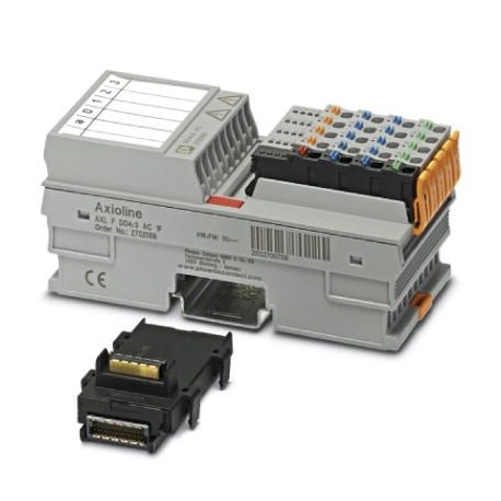
AXL F DO4/3 AC 1F 2702068 PHOENIX CONTACT I/O module
$0.00米ドル
3003 在庫あり
主な仕様
GTIN:4046356933087
注文キー:2702068
カタログページ:Page 110 (C-6-2017)
梱包単位:1 pc
サプライヤー情報
製品: 0
通常、2〜3営業日以内に出荷します
品質保証済み
高速配送
テクニカルサポート
技術仕様
| パラメータ | 価値 |
|---|---|
| GTIN | 4046356933087 |
| 注文キー | 2702068 |
| カタログページ | Page 110 (C-6-2017) |
| 梱包単位 | 1 pc |
| (寸法) | -25 °C ... 50 °C (max. 2 A/channel for any mounting position) |
| 原産国 | DE (Germany) |
| (デジタル出力) | I/O area AC / PE 4 kV Rated surge voltage (basic insulation according to EN 61010-2-201/IEC 61010-2-201) |
| 関税番号 | 85389091 |
| 指定(一般) | Axioline F local bus |
| (電気的絶縁) | IEC 61850-3 Attenuated oscillating waves, EN 61000-4-18/IEC 61000-4-18 1 kV symmetrical, 2.5 kV asymmetrical |
| 保護(インターフェース) | max. 8 A |
| 指定(インターフェース) | Supply for digital output modules (UO) |
| チャンネル数(一般) | 2 |
| 接続方法(一般) | Bus base module |
| 深さ(主要な商業データ) | 54 mm |
| 供給電圧(インターフェース) | 230 V AC |
| 幅(主要商業データ) | 53.6 mm |
| (基準および規制) | No hazardous substances above threshold values |
| 高さ(主要商業データ) | 126.1 mm |
| 正味重量(接続データ) | 239 g |
| 伝送速度(一般) | 100 Mbps |
| 消費電力(インターフェース) | max. 2024 VA (of which 8 VA internal losses) |
| テストセクション(デジタル出力) | I/Os / logic 4 kV Rated surge voltage (safe isolation according to EN 61010-2-201/IEC 61010-2-201) |
| 取り付けタイプ(接続データ) | DIN rail |
| 保護の種類(インターフェース) | Surge protection of the supply voltage |
| 消費電流(インターフェース) | max. 8 A (provide external protection) |
| 指定(周囲条件) | Axioline F connector |
| 保護等級(寸法) | IP20 |
| 出力名(軸線ポテンシャル) | Digital outputs |
| 供給電圧範囲(インターフェース) | 12 V AC ... 253 V AC (including all tolerances, including ripple, 50 ... 60 Hz) |
| 出力電圧(アキシオライン電位) | 230 V AC |
| 1個あたりの重量(梱包を除く) | 239.000 g |
| 空気圧(動作)(寸法) | 70 kPa ... 106 kPa (up to 3000 m above sea level) |
| 剥離長さ(周囲条件) | 8 mm |
| 中国RoHS(規格と規制) | Environmentally friendly use period: unlimited = EFUP-e |
| 接続方法(周囲条件) | Push-in connection |
| 接続方法(軸線電位) | Push-in connection |
| 機械試験(電気絶縁) | Vibration resistance in acc. with EN 60068-2-6/IEC 60068-2-6 5g |
| 出力数(Axiolineポテンシャル) | 4 (Triac outputs with zero voltage switch) |
| 寸法に関する注記(主要商業データ) | The depth is valid when a TH 35-7,5 DIN rail is used (according to EN 60715). |
| 保護の種類(アキシオリン電位) | External protection required |
| 寸法図(主要商品データ) | |
| 公称負荷、抵抗(Axioline電位) | max. 460 W (at nominal voltage) |
| 接続技術(Axiolineポテンシャル) | 3-wire |
| 周囲温度(動作)(寸法) | -25 °C ... 60 °C (max. 2 A/channel for wall mounting on horizontal DIN rail; max. 1 A/channel for any mounting position) |
| 公称出力電圧(Axioline電位) | 230 V AC |
| 空気圧(保管・輸送)(寸法) | 70 kPa ... 106 kPa (up to 3000 m above sea level) |
| 許容湿度(動作)(寸法) | 5 % ... 95 % (non-condensing) |
| 重量仕様に関する注意事項(接続データ) | with connectors and bus base module |
| 接続方法に関する注意(周囲条件) | Please observe the information provided on conductor cross sections in the “Axioline F: system and installation” user manual.When selecting the cables, please note that in the case of a small conductor cross section and high current, the terminal point temperature may be up to 30 K above the ambient temperature. |
| 周囲温度(保管/輸送)(寸法) | -40 °C ... 85 °C |
| 導体断面積 AWG 最大(周囲条件) | 16 |
| 導体断面積AWG最小値(周囲条件) | 20 |
| 許容湿度(保管・輸送)(寸法) | 5 % ... 95 % (non-condensing) |
| 標準規格(電気絶縁)に従って開発 | IEC 61850-3 Immunity to magnetic fields, EN 61000-4-8/IEC 61000-4-8 300 A/m continuous, 1000 A/m for 1 s |
| 導体断面積(固体最大)(周囲条件) | 1.5 mm² |
| 導体断面積(最小)(周囲条件) | 0.5 mm² |
| モジュールあたりの最大出力電流(Axioline電位) | 8 A AC (provide external protection) |
| チャネルあたりの最大出力電流(Axioline電位) | 2 A AC |
| 導体断面積最大可とう性(周囲条件) | 1.5 mm² |
| 導体断面積の最小値(周囲条件) | 0.5 mm² |
製品説明
AxiolineF, Digital output module, Digital outputs:4 (Triac outputs with zero voltage switch), 230 VAC, 2 A, connection technology:3 conductors, transmission speed on the local bus:100 MBit/s, protecti
主な機能
- 産業グレードの品質
- RoHS準拠
- CE認証取得
- 1年保証
製品資料
データシート
技術仕様と性能データ
ユーザーマニュアル
設置・操作ガイド


