在庫あり 注目商品
PSR-PC40-2NO-1DO-24DC-SC
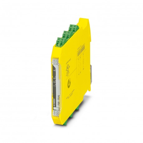
PSR-PC40-2NO-1DO-24DC-SC 2700588 PHOENIX CONTACT Coupling relay
$0.00米ドル
3654 在庫あり
主な仕様
:High demand
深さ:114.5 mm
ショック:15g
幅:12.5 mm
サプライヤー情報
製品: 0
通常、2〜3営業日以内に出荷します
品質保証済み
高速配送
テクニカルサポート
技術仕様
| パラメータ | 価値 |
|---|---|
| High demand | |
| 深さ | 114.5 mm |
| ショック | 15g |
| 幅 | 12.5 mm |
| 身長 | 112.2 mm |
| 現在 | max. 100 mA |
| 電圧 | approx. 22 V DC (Us- 2 V) |
| プラグイン可能 | yes |
| CCCexノート | Use in potentially explosive areas is not permitted in China. |
| リレータイプ | Electromechanical relay with force-guided contacts in accordance with IEC/EN 61810-3 |
| 応用 | Safe switch off |
| 証明書 | UL 22 ATEX 2912X |
| 指定 | A1/A2 |
| フィルター時間 | max. 2 ms (at A1-A2; test pulse width) |
| 出力ヒューズ | 6 A gL/gG |
| 製品タイプ | Coupling relay |
| ねじ山 | M3 |
| 組み立てノート | See derating curve |
| 取り付けタイプ | DIN rail mounting |
| 回復時間 | 500 ms |
| 停止カテゴリ | 0 |
| 識別 | II 3G Ex ec nC IIC T4 Gc |
| 突入電流 | typ. 400 mA (Δt s) |
| 製品ファミリー | PSRmini |
| ステータス表示 | 2 x LED (green) |
| カラー(ハウジング) | yellow (RAL 1018) |
| 記事の改訂 | 07 |
| 接触材料 | AgSnO2 |
| エラー表示 | 1 x LED (red) |
| ハウジング材質 | Polyamide |
| 最大高度 | ≤ 2000 m (Above sea level) |
| 入力数 | 2 (Non-safety-related start inputs: Y1/Y2) |
| 剥ぎ取り長さ | 7 mm |
| 接続方法 | Screw connection |
| 取り付け位置 | vertical, horizontal, with front of module upward |
| 出力数 | 2 (safety-related N/O contacts: 13/14, 23/24) |
| 平方総電流 | 60 A2(observe derating) |
| スイッチング電圧 | min. 12 V AC/DC |
| 締め付けトルク | 0.5 Nm ... 0.6 Nm |
| 出力の説明 | 2 NO contacts each in series, without delay, floating |
| 保護回路 | Serial protection against polarity reversal; 33 V suppressor diode |
| スイッチング容量 | min. 60 mW |
| 消費電流 | < 5 mA |
| 申請に関する注意事項 | Only for industrial use |
| スイッチング周波数 | max. 0.5 Hz |
| 保護の程度 | IP20 |
| 典型的なリリース時間 | < 35 ms (when controlled via A1) |
| 規格・規制 | EN 60664-1, EN 60079-7, EN 60079-15 |
| 振動(操作) | 10 Hz ... 150 Hz, 2g |
| 接点スイッチングタイプ | 2 enabling current paths |
| 最大突入電流 | 500 mA (Δt = 1 ms at Us) |
| 公称動作モード | 100% operating factor |
| 機械の耐用年数 | 10x 106cycles |
| 米国の電力消費量 | typ. 1.8 W |
| 定格絶縁電圧 | 250 V AC |
| 短絡保護 | no |
| 動作電圧表示 | 1 x yellow LED |
| 弊社での開始時間(標準) | < 200 ms (when controlled via A1, automatic start) |
| 導体断面積AWG | 24 ... 12 |
| 連続電流の制限 | 6 A (High demand) |
| 安全度水準(SIL) | 3 |
| 導体断面積は剛性 | 0.2 mm² ... 2.5 mm² |
| 定格サージ電圧/絶縁 | Safe isolation, 6 kV reinforced insulation from control circuit, start circuit, signal output to the enabling current paths, 4 kV/basic insulation between the enabling current paths and between all current paths and housing |
| 周囲温度(動作) | -40 °C ... 70 °C (observe derating) |
| 定格制御電源電流 IS | typ. 75 mA (depending on load M1 +100 mA) |
| 導体断面積が柔軟 | 0.2 mm² ... 2.5 mm² |
| 周囲温度(保管/輸送) | -40 °C ... 85 °C |
| 定格制御回路電源電圧(米国) | 20.4 V DC ... 26.4 V DC |
| 設備設置場所の最小保護等級 | IP54 |
| 入力/始動およびフィードバック回路の電圧 | 24 V DC -15 %; +10 % |
| 最大許容湿度(保管/輸送) | 75 % (on average, 85% infrequently, non-condensing) |
| 最大許容全導体抵抗 | 150 Ω |
| 最大許容相対湿度(動作) | 75 % (on average, 85% infrequently, non-condensing) |
| 公称条件での最大消費電力 | 5.5 W (IL² = 60 A²) |
| IEC 60947-5-1に準拠したスイッチング容量 | 4 A (24 V (DC13)) |
製品説明
Coupling relay for high and low demand applications SIL 3, couples digital output signals to the periphery, 2 trip circuits, 1 digital warning output, Safe-State-Off applications, test pulse filter, p
主な機能
- 産業グレードの品質
- RoHS準拠
- CE認証取得
- 1年保証
製品資料
データシート
技術仕様と性能データ
ユーザーマニュアル
設置・操作ガイド


