在庫あり 注目商品
F3SJ-A0533P14
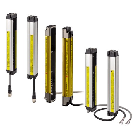
F3SJ-A0533P14 F3SJ0057D 232586 OMRON Class IV Advanced Finger 533mm Serial Connection
$0.00米ドル
3679 在庫あり
主な仕様
1,631 (F3SJ-A____P14/P30):180
型式(F3SJ-A____P14/P30):Protected height (mm)
材質(F3SJ-A____P14/P30):Casing (including metal parts on both ends): Aluminum, zinc die-castCap: ABS resin, Optical cover: PMMA resin (acrylic), Cable: Oil resistant PVC
受信機(F3SJ-A____P14/P30):Light intensity level indicators (green LED × 2, orange LED × 3): ON based on the light intensityError mode indicators (red LED × 3): Blink to indicate error detailsOFF output indicator (red LED × 1): ON when safety output is OFF, blinks at lockout.ON output indicator (green LED × 1): ON while safety output is ONMuting error indicator, Blanking/test indicator (green LED × 2): ON/flash according to function
サプライヤー情報
OMRON
製品: 41472
通常、2〜3営業日以内に出荷します
品質保証済み
高速配送
テクニカルサポート
技術仕様
| パラメータ | 価値 |
|---|---|
| 1,631 (F3SJ-A____P14/P30) | 180 |
| 型式(F3SJ-A____P14/P30) | Protected height (mm) |
| 材質(F3SJ-A____P14/P30) | Casing (including metal parts on both ends): Aluminum, zinc die-castCap: ABS resin, Optical cover: PMMA resin (acrylic), Cable: Oil resistant PVC |
| 受信機(F3SJ-A____P14/P30) | Light intensity level indicators (green LED × 2, orange LED × 3): ON based on the light intensityError mode indicators (red LED × 3): Blink to indicate error detailsOFF output indicator (red LED × 1): ON when safety output is OFF, blinks at lockout.ON output indicator (green LED × 1): ON while safety output is ONMuting error indicator, Blanking/test indicator (green LED × 2): ON/flash according to function |
| 状態 (F3SJ-A____P14/P30) | 1 set |
| インジケーター(F3SJ-A____P14/P30) | Emitter |
| 281~389 (F3SJ-A____P14/P30) | 30 to 42 |
| 407~497 (F3SJ-A____P14/P30) | 44 to 54 |
| 420~720(F3SJ-A____P14/P30) | 17 to 29 |
| 515から605(F3SJ-A____P14/P30) | 56 to 66 |
| 623から731 (F3SJ-A____P14/P30) | 68 to 80 |
| 767から983 (F3SJ-A____P14/P30) | 84 to 108 |
| アクセサリー(F3SJ-A____P14/P30) | Test rod (*1), instruction manual, standard mounting bracket (F39-LJ1 bracket for top/bottom mounting), mounting brackets (intermediate) (*2), error mode label, User's Manual (CD-ROM)*1. The F3SJ-A☐☐☐☐55 is not included.*2. Number of intermediate brackets depends on protective height of F3SJ.For protective height from 600 to 1,130 mm : 1 set for each of the emitter and receiver is includedFor protective height from 1,136 to 1,658 mm: 2 sets for each of the emitter and receiver are includedFor protective height from 1,660 to 2,180 mm : 3 sets for each of the emitter and receiver are includedFor protective height from 2,195 to 2,500 mm : 4 sets for each of the emitter and receiver are included |
| 745から1,045(F3SJ-A____P14/P30) | 30 to 42 |
| 入力電圧(F3SJ-A____P14/P30) | Test input, interlock selection input, reset input, and muting input are allON voltage: 9 to 24 V (Vs) (sink current: 3 mA max.), OFF voltage: 0 to 1.5 V, or openExternal device monitoring inputON voltage: 9 to 24 V (Vs) (sink current: 5 mA max.), OFF voltage: 0 to 1.5 V, or open |
| テスト機能(F3SJ-A____P14/P30) | Self test (at power-ON and at power distribution)External test (emission stop function by test input) |
| 1,055から1,271(F3SJ-A____P14/P30) | 116 to 140 |
| 1,070~1,295(F3SJ-A____P14/P30) | 43 to 52 |
| 1,343から1,559(F3SJ-A____P14/P30) | 148 to 172 |
| 1,395から1,620(F3SJ-A____P14/P30) | 56 to 65 |
| 1,745から1,995(F3SJ-A____P14/P30) | 70 to 80 |
| 2,120~2,495(F3SJ-A____P14/P30) | 85 to 100 |
| 10 (仕様と注文情報) | 245 |
| 12 (仕様と注文情報) | 295 |
| 16 (仕様と注文情報) | 395 |
| 19 (仕様と注文情報) | 470 |
| 21 (仕様と注文情報) | 520 |
| 22 (仕様と注文情報) | 545 |
| 23 (仕様と注文情報) | 570 |
| 25 (仕様と注文情報) | 620 |
| 26 (仕様と注文情報) | 245 |
| 28 (仕様と注文情報) | 263 |
| 29 (仕様と注文情報) | 720 |
| 32 (仕様と注文情報) | 795 |
| 34 (仕様と注文情報) | 317 |
| 35 (仕様と注文情報) | 870 |
| 37 (仕様と注文情報) | 920 |
| 38 (仕様と注文情報) | 945 |
| 41 (仕様と注文情報) | 1,020 |
| 42 (仕様と注文情報) | 389 |
| 44 (仕様と注文情報) | 1,095 |
| 45(仕様と注文情報) | 1,120 |
| 48 (仕様と注文情報) | 1,195 |
| 50 (仕様と注文情報) | 461 |
| 51 (仕様と注文情報) | 1,270 |
| 56 (仕様と注文情報) | 1,395 |
| 60 (仕様と注文情報) | 551 |
| 65 (仕様と注文情報) | 1,620 |
| 68 (仕様と注文情報) | 623 |
| 70 (仕様と注文情報) | 1,745 |
| 75 (仕様と注文情報) | 1,870 |
| 76 (仕様と注文情報) | 695 |
| 80 (仕様と注文情報) | 1,995 |
| 88 (仕様と注文情報) | 803 |
| 90 (仕様と注文情報) | 2,245 |
| 95 (仕様と注文情報) | 2,370 |
| 96 (仕様と注文情報) | 875 |
| 100 (仕様と注文情報) | 2,495 |
| 108 (仕様と注文情報) | 983 |
| 116 (仕様と注文情報) | 1,055 |
| 124 (仕様と注文情報) | 1,127 |
| 132 (仕様と注文情報) | 1,199 |
| 140 (仕様と注文情報) | 1,271 |
| 周囲湿度(F3SJ-A____P14/P30) | Operating: 35% to 85% (no condensation), Storage: 35% to 95% |
| 耐衝撃性(F3SJ-A____P14/P30) | Malfunction: 100 m/s2, 1,000 times each in X, Y, and Z directions |
| 接続方法(F3SJ-A____P14/P30) | Connector method (M12, 8-pin) |
| 直列接続(F3SJ-A____P14/P30) | Time division emission by series connectionNumber of connections: up to 4 sets (F3SJ-A only) F3SJ-E, F3SJ-B and F3SJ-TS cannot be connected.Total number of beams: up to 400 beamsMaximum cable length for 2 sets: no longer than 15 m |
| 重量(梱包時)(F3SJ-A____P14/P30) | Calculate using the following expressions:(1) For F3SJ-A____14, weight (g) = (protective height) x 1.7 +α(2) F3SJ-A____30, weight (g) = (protective height) x 1.5 +αThe values forαare as follows:Protected height 245 to 596 mm: = 1,100 protected height 1,660 to 2,180 mm: = 2,400Protected height 600 to 1,130 mm: = 1,500 protected height 2,195 to 2,500 mm: = 2,600Protected height 1,136 to 1,658 mm: = 2,000 |
| 耐電圧(F3SJ-A____P14/P30) | 1,000 VAC 50/60 Hz, 1 min |
| 保護回路(F3SJ-A____P14/P30) | Output short-circuit protection, and power supply reverse polarity protection |
| 周囲温度(F3SJ-A____P14/P30) | Operating: -10 to 55°C (no icing), Storage: -30 to 70°C |
| F3SJ-A____14シリーズ(F3SJ-A____P14/P30) | 245 to 263 |
| F3SJ-A____30シリーズ(F3SJ-A____P14/P30) | 245 to 395 |
| 適用規格(F3SJ-A____P14/P30) | IEC 61496-1, EN 61496-1 UL 61496-1, Type 4 ESPE (Electro-Sensitive Protective Equipment)IEC 61496-2, CLC/TS 61496-2, UL 61496-2, Type 4 AOPD (Active Opto-electronic Protective Devices)IEC 61508-1 to -3, EN 61508-1 to -3 SIL3IEC 13849-1: 2006, EN ISO 13849-1: 2008 (PLe, Cat.4)UL 508, UL 1998, CAN/CSA C22.2 No.14, CAN/CSA C22.2 No.0.8 |
| 保護等級(F3SJ-A____P14/P30) | IP65 (IEC 60529) |
| 耐振動性(F3SJ-A____P14/P30) | Malfunction: 10 to 55 Hz, Multiple amplitude of 0.7 mm, 20 sweeps in X, Y, and Z directions |
| 絶縁抵抗(F3SJ-A____P14/P30) | 20 MΩ min. (at 500 VDC) |
| 0.2~7 m(仕様と注文情報) | 1,745 to 2,495 |
| アプリケーション(仕様と注文情報) | Detection capability |
| 安全関連機能(F3SJ-A____P14/P30) | Start interlock, restart interlock (Must be set with a setting tool when the muting function is used.)External device monitorMuting (Lamp burnout detection, override function included. F39-CN6 key cap for muting is required.)Fixed blanking (must be set by a setting tool)Floating blanking (must be set by a setting tool) |
| 白熱電球不使用(F3SJ-A____P14/P30) | 100 m |
| 梁の数(仕様と注文情報) | Protective height (mm)2 |
| 指保護(仕様と注文情報) | Dia. 14 mm |
| 手/腕の保護(仕様と注文情報) | Dia. 30 mm |
| 動作周囲光強度(F3SJ-A____P14/P30) | Incandescent lamp: receiving-surface light intensity of 3,000 lx max., Sunlight: receiving-surface light intensity of 10,000 lx max. |
| 相互干渉防止機能(F3SJ-A____P14/P30) | Interference light prevention algorithm, sensing distance change function |
| (シングルエンドコネクタケーブル(送信機用と受信機用の2本1組)) | Laser pointer for F3SJ |
| 外部表示灯出力1に白熱ランプを使用する(F3SJ-A____P14/P30) | 60 m |
| 外部表示灯出力2に白熱ランプを使用する(F3SJ-A____P14/P30) | 40 m |
| 7 m (片端コネクタケーブル (送信機用と受信機用の 2 本 1 セット)) | F39-JD7A |
| 10 m (片端コネクタケーブル (送信機用と受信機用の2本1組)) | F39-JD10A |
| 15 m (片端コネクタケーブル (送信機用と受信機用の2本1組)) | F39-JD15A |
| 20 m (片端コネクタケーブル (送信機用と受信機用の2本1組)) | F39-JD20A |
| モデル(シングルエンドコネクタケーブル(送信機用と受信機用の2本1セット)) | F3SJ-A____P14 |
| エミッター(シングルエンドコネクタケーブル(エミッター用とレシーバー用の2本1組)) | Auxiliary output 2: Turns ON when the point of 30,000 operating hours is reached (Operation mode can be changed with the setting tool.)External indicator output 2 : ON when lock-out for a basic system (Operation mode can be changed with the setting tool.)ON when muting/override for a muting system (Operation mode can be changed with the setting tool.) |
| バージョン(シングルエンドコネクタケーブル(送信機用と受信機用の2本1セット)) | Ver. 2 |
| 受信機(シングルエンドコネクタケーブル(送信機用と受信機用の2本1組)) | To 50 beams: 68 mA max., 51 to 100 beams: 90 mA max., 101 to 150 beams: 111 mA max.,151 to 180 beams: 128 mA max., 201 to 234 beams: 142 mA max. |
| OFFからON(シングルエンドコネクタケーブル(エミッターとレシーバー用の2本1組)) | 1 set,0245 to 983: 44 ms to 70 ms max.1,055 or higher: 80 ms to 100 ms max. |
| 外観(片端コネクタケーブル(送信機用と受信機用の2本1組)) | Output |
| センサータイプ(片端コネクタケーブル(エミッター用とレシーバー用の2本1組)) | Type 4 safety light curtain |
| ビームギャップ(P)(片端コネクタケーブル(投光器用と受光器用の2本1組)) | 9 mm |
| レンズ径(片端コネクタケーブル(送信機用と受信機用の2本1組)) | Diameter 5 mm |
| 動作範囲(片端コネクタケーブル(送信機用と受信機用の2本1組)) | 0.2 to 9 m (protective height 1,640 mm max.), 0.2 to 7 m (protective height 1,655 mm min.)(Depending on the setting tool, the detection distance can be shortened to 0.5 m.) |
| 安全カテゴリー(片端コネクタケーブル(送信機用と受信機用の2本1組)) | Safety purpose of category 4, 3, 2, 1, or B |
| ビーム数(n)(片端コネクタケーブル(投光器用と受光器用で2本ずつ)) | 26 to 180 |
| 検出機能(片端コネクタケーブル(送信機用と受信機用の2本1組)) | Opaque objects 14 mm in diameter |
| 起動待ち時間(片端コネクタケーブル(送信機用と受信機用の2本1組)) | 2 s max. (2.2 s max. for series connection) |
| 補助出力および外部表示灯出力に白熱ランプを使用する(F3SJ-A____P14/P30) | 45 m |
| 出力動作モード(シングルエンドコネクタケーブル(送信機用と受信機用の2本1組)) | Receiver |
| 安全出力(OSSD)(片端コネクタケーブル(投光器用と受光器用で2本ずつ)) | Two PNP transistor outputs, load current 300 mA max., residual voltage 2 V max. (except for voltage drop due to cable extension),allowable capacity load 2.2 μF, leak current 1 mA max.(This can be different from traditional logic (ON/OFF) because safety circuit is used.) |
| 保護高さ(PH)(片端コネクタケーブル(投光器と受光器用2本1組)) | 245 to 1,631 mm |
| 設定ツール接続(片端コネクタケーブル(投光器用と受光器用の2本1組)) | Connectable |
| 電源電圧(Vs)(シングルエンドコネクタケーブル(送信機用と受信機用の2本1組)) | 24 VDC±20% (ripple p-p10% max.) |
| 消費電流(無負荷)(片端コネクタケーブル(送信機用と受信機用の2本1組)) | Emitter |
| 有効開口角(EAA)(片端コネクタケーブル(送信機用と受信機用の2本1組)) | Based on IEC 61496-2.Within±2.5° for both emitter and receiver when the detection distance is 3 m or over |
| 光源(発光波長)(片端コネクタケーブル(発光部用と受光部用の2本1組)) | Infrared LED (870 nm) |
| 補助出力1(非安全出力)(片端コネクタケーブル(投光器用と受光器用で2本1組)) | One PNP transistor output, load current 300 mA max., residual voltage 2 V max. (except for voltage drop due to cable extension),leak current 1 mA max. |
| 外部表示出力(非安全出力)(片端コネクタケーブル(投光器用と受光器用の2本1組)) | Available indicatorsIncandescent lamp : 24 VDC, 3 to 7 WLED lamp: Load current 10 mA to 300 mA max., leak current 1 mA max.(To use an external indicator, an F39-JJ3N universal indicator cable or an F39-A01P-PAC dedicated external indicator kit is required.) |
| 応答時間(安定した光入射条件下)(片端コネクタケーブル(投光器用と受光器用の2本1組)) | ON to OFF |
| 補助出力2(非安全出力。基本システム用機能。)(片端コネクタケーブル(投光器用と受光器用で2本1組)) | One PNP transistor output, load current 50 mA max., residual voltage 2 V max. (except for voltage drop due to cable extension),leak current 1 mA max. |
製品説明
More details
主な機能
- 産業グレードの品質
- RoHS準拠
- CE認証取得
- 1年保証
技術的詳細
Application
製品資料
データシート
技術仕様と性能データ
ユーザーマニュアル
設置・操作ガイド


